| 品牌:3M | 型号:72-N1 | 线芯材质:裸铜线 |
| 电压等级:中、低压电力电缆(35千伏及以下) | 绝缘材料:塑料绝缘电力电缆 | 用途:低压电缆中间接头 |
| 产品认证:***-2000 |
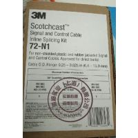
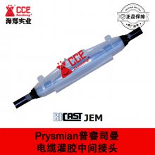
3M Scotchcast Inline Splicing Kits 72-N1电缆中间接头
3M Scotchcast Inline Splicing Kits 72-N2电缆中间接头
3M Scotchcast Inline Splicing Kits 72-N3电缆中间接头
3M Scotchcast Inline Splicing Kits 72-N4电缆中间接头
3M Scotchcast Inline Splicing Kits 72-N5电缆中间接头
3M Scotchcast Inline Splicing Kits 72-N6电缆中间接头

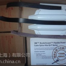
Data Sheet
Product Description
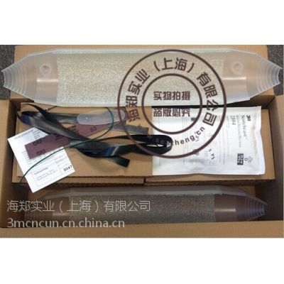
3M? Scotchcast? Inline Splicing Kits 72-N Series is a series of rigid body splices tailored for joining signal and control cables. The kits are designed to accommodate shielded or unshielded constructions of plastic or rubber-jacketed cables. Six kit sizes cover a range of cables up to 100-pair (200 conductors) 10 AWG or 200-pair (400 conductors) 22 AWG.
The 72-N series splice consists of a rigid-body mold filled with pliable polyurethane 3M Scotchcast Electrical Insulating and Sealing Compound 2104.
Jumper wires with clips provide for shield continuity on shielded cables. Built-in spacer webbing automatically provides for cable centering and proper compound coverage. The kits are sized for, but do not include, 3M? Scotchlok? Insulated Butt Connectors. The completed splice is designed and tested for direct burial.
Kit Contents
Each kit contains sufficient quantities of the following materials to make one (1) splice, excluding inline connectors:
? One two-part translucent mold body with tongue and groove seams and built-in spacer webbing
? 3M? Scotchcast? Electrical Insulating and Sealing Compound 2104 in convenient 3M closed mixing pouch
? Two pour spouts for kits 72-N1, 72-N2, and 72-N3; one top cap cover for kits 72-N4, 72-N5 and 72-N6
? Scotch? Rubber Splicing Tape 23 for constructing sealing collars and sealing splice body ends
? One nonconductive abrasive cloth for preparing cable
? One bonding (jumper) wire with clips for providing solderless shield continuity on shielded cables (except 72-N1 kit)
? Instructions showing proper installation techniques for shielded and unshielded signal and control cables
? The 72-N2 through 72-N6 kits will accommodate shielded or unshielded cable. The 72-N1 kit is recommended for unshielded cable only
? Convenient kits simplify ordering and stocking
? Kits provide all materials needed to reinsulate, reconnect shield, and rejacket one splice
? Compound has low viscosity for fast, complete filling of splice
? Compound has low exotherm which will not damage plastic insulated cable
? Convenient closed mixing pouch container permits clean, easy compound handling
? Polypropylene mold with built-in spacer web automatically provides for cable centering and compound coverage
? No special tools required; normal hand tools only
Applications
To splice signal and control cables rated up to 1000 volts, sized 0.25–3.25" (6.4–82.6 mm) O.D.
? For inline splicing of shielded or unshielded cables
? For use on plastic or rubber jacketed cables
? For use on cables with plastic or rubber insulated conductors
? For use in direct burial applications
? For use with underground systems
— Manhole
— Handhole
— Junction box
? For use in indoor applications
— Vault
— Cable tray
— Junction box
— Duct
Splice Features | ? For joining of cable reel-ends | |
? For repair of cable failures and dig-ins | ||
? Versatility is designed into each kit to allow a wide range of cable sizes
Moisture-Resistance Test
Thermal cycling submerged in water pressurized to simulate a 1.8 m (6') head: the splice 72-N series exceeds 1.0-x-106 ohms insulation resistance after ten temperature cycles of 2°C to 24°C (35°F to 75°F).
Splice Selection Guide
Specification
Product
(open specification)
Signal and control cable splices must be capable of normal continuous operation at 1000 volts. The splices must consist of a rigid polypropylene mold body with a built-in spacer web to automatically provide for cable
centering and proper compound coverage; the mold body shall be filled with a flexible polyurethane electrical compound capable of continuous operation at 90°C (194°F), with an emergency overload temperature rating of 130°C (266°F).
Splices must have provisions for inline splicing of shielded or unshielded, plastic or rubber jacketed, plastic or rubber insulated, signal and control cables. The splices shall be rated for direct burial applications.
Engineering/Architectural
(closed specification)
Splicing of all signal and control cables rated at 1000 volts or less and sized with an outside diameter of 0.25"–3.25" (6.4–82.6 mm) shall be performed in accordance with the instructions provided with 3M Scotchcast Signal and Control Cable Inline Splicing Kit 72-N Series.
Installation Techniques
The exact instructions for constructing each splice are packed in each kit. The following summarizes these instructions:
1. Prepare cable to dimension “A” for splice opening, removing shielding and core wrapper according to steps for shielded cable or unshielded cable, as applicable.
2. Install 3M? Scotchlok? Insulated Butt Connectors, not provided, staggering individually or in pairs. Observe color coding.
3. Install jumper bonding wire to shielded cables; construct sealing collars with Scotch? Rubber Tape 23 provided.
4. Trim mold body ends to fit cable and install over splice.
5. Seal mold ends with Scotch Tape 23 provided.
6. Install pour spouts into kits 72-N1, 72-N2 and 72-N3.
7. Mix 3M Scotchcast 2104 compound and pour into splice body, filling completely. Allow compound to cure.
Maintenance
The components within this kit are stable under normal storage conditions. Normal storage and stock rotation are recommended.
The 2104 compound is not impaired by freezing; however, it should be warmed to 0°C (32°F) before being mixed and poured.
CAUTION
Working around energized electrical systems may cause serious injury or death. Installation should be performed by personnel familiar with good safety practice in handling electrical equipment. De-energize and ground all electrical systems before installing product.
3M, Scotchcast and Scotchlok are trademarks of 3M Company. Scotch is a registered trademark of 3M Company.
Important Notice
All statements, technical information, and recommendations related to 3M’s products are based on information believed to be reliable, but the accuracy or completeness is not guaranteed. Before using this product, you must evaluate it and determine if it is suitable for your intended application. You assume all risks and liability associated with such use. Any statements related to the product which are not contained in 3M’s current publications, or any contrary statements contained on your purchase order shall have no force or effect unless expressly agreed upon, in writing, by an authorized officer of 3M.
Warranty; Limited Remedy; Limited Liability.
This product will be free from defects in material and manufacture for a period of one (1) year from the time of purchase. 3M MAKES NO
OTHER WARRANTIES INCLUDING, BUT NOT LIMITED TO, ANY IMPLIED WARRANTY OF MERCHANTABILITY OR FITNESS FOR A PARTICULAR PURPOSE. If this product is defective within the warranty period stated above, your exclusive remedy shall be, at 3M’s option, to replace or repair the 3M product or refund the purchase price of the 3M product. Except where prohibited by law, 3M will not
be liable for any indirect, special, incidental or consequential loss or damage arising from this 3M product, regardless of the legal theory asserted.